Sandbox models with high-displacement thrust faults compared to features of some Canadian Rockies sections
by Philip S. Prince
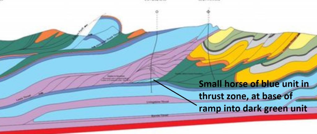
Sandbox models don’t always produce the geometry the modeler wants, but with properly scaled materials, a “failed” model run can still produce worthy analog structures. I recently came up short on attempts to model some details of the southern Appalachian Valley and Ridge, instead producing structures reminiscent of some well-known Canadian Rockies sections. The Alberta section shown below was most recently (I think?) published in Mackay (2015), though I am unsure of its original origin (it can be viewed here without journal access). This section shows some interesting fault zone and thrust footwall details that unexpectedly popped up in my slightly-off-the-mark models. Note that the models don’t replicate the entirety of this section; they just reflect some of the structural styles characteristic of fold-thrust belts with high-displacement thrusts.
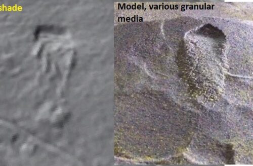
A favorite detail of this section is the thin “horse” block (an entirely fault-bounded piece of stratigraphy within a fault zone) being dragged along in the Lewis Thrust zone. If you look closely, you can see that the horse was penetrated by a well, which is presumably how its existence was confirmed. A zoomed look at the horse is shown below.
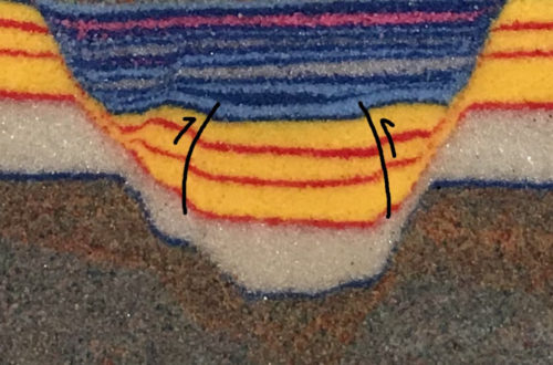
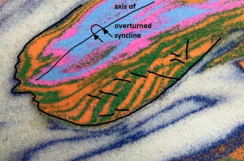
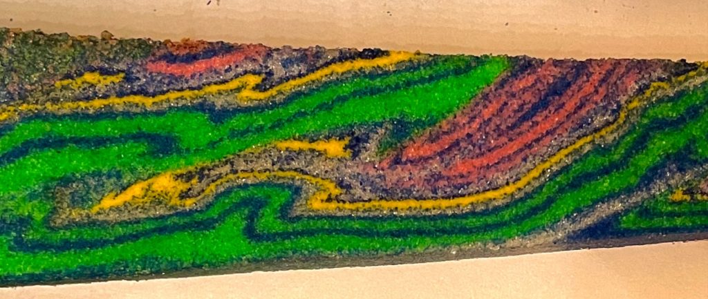
The model shown below contains a comparable small horse detached from the yellow layer in the footwall of the overlying large, high-displacement thrust sheet. This model horse consists entirely of the yellow bed and the thin, dark blue layer intended to highlight the yellow bed’s boundaries. Despite being folded on top of itself in a tight, overturned syncline, the horse is too thin to significantly arch the overlying thrust sheet, making its presence unnoticeable from the surface of the model.

The thin yellow horse developed because the brittle yellow bed (dolomite sand; pink and green are quartz) is bounded above and below by glass microbead detachment layers. These weak bounding layers permit small sections of the single brittle yellow layer to be “torn off” of a footwall ramp and carried along within a thrust zone. Removal and transport of the horse occurred after the overlying thrust fault had already accumulated notable displacement–the horse is much closer to its own footwall cut-off than the leading edge of the green thrust sheet it to its footwall ramp. The position of the high-displacement thrust sheet’s ramp relative to the horse’s origin is apparent when the entire model wedge is shown.

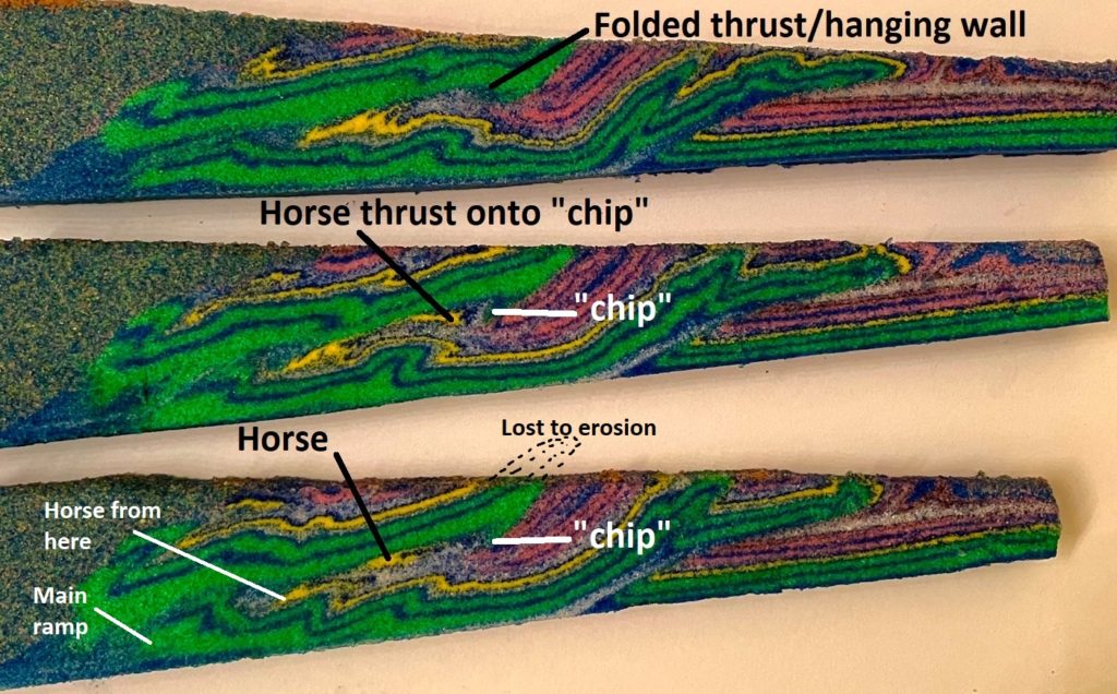
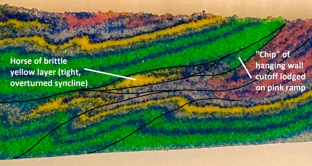
Other sections in this model showed a similar horse which had experienced more transport and lodged against the “chip” of green hanging wall strata stuck on the pink ramp. The model images below show this relationship–compare it to the previous horse images, where the horse has not yet reached the ramp zone.

This model section is interesting because the yellow horse is thrust onto older green layers of the “chip.” This relationship is possible because the green chip lodged early in the thrust sequence, with the yellow horse being detached, transported, and lodged later. I would be interested to know if relationships like this have been drilled through (or otherwise observed) in the Canadian Rockies section shown at the beginning of the post. The southern Appalachian Valley and Ridge hosts this type of geometry in several locations where numerous ramps and flat exists within the imbricated sedimentary section.
A second model produced a deep, sub-thrust ramp anticline similar to a feature beneath the Livingstone Thrust in the Canadian Rockies section.


While the model ramp anticline lacks the significant thrust displacement associated with the “real-life” structure, it produces no significant surface expression in the overlying thrust sheet, similar to the real anticline. Much like the small horse in the earlier example, the presence of the deep ramp anticline would not be immediately obvious from surface observation, particularly without some overall geometric constraints on the thrust belt’s architecture, such as its overall thickness. The presence of blind features like these beneath high-displacement thrust structures makes interpretation in thrust systems with many detachment horizons particularly challenging.
The “deep anticline” model also produced an interesting pair of anticlines near the hanging wall cutoff of the overlying, high-displacement thrust sheet. One anticline is associated with the cutoff of the deepest layer of the thrust sheet, while the second is developed by drag along the thrust.
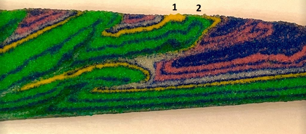
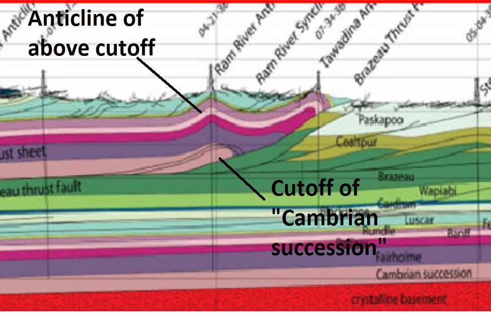
This geometry was reminiscent of the Ram River Anticline of the Brazeau Thrust system, shown below in a section sourced here.
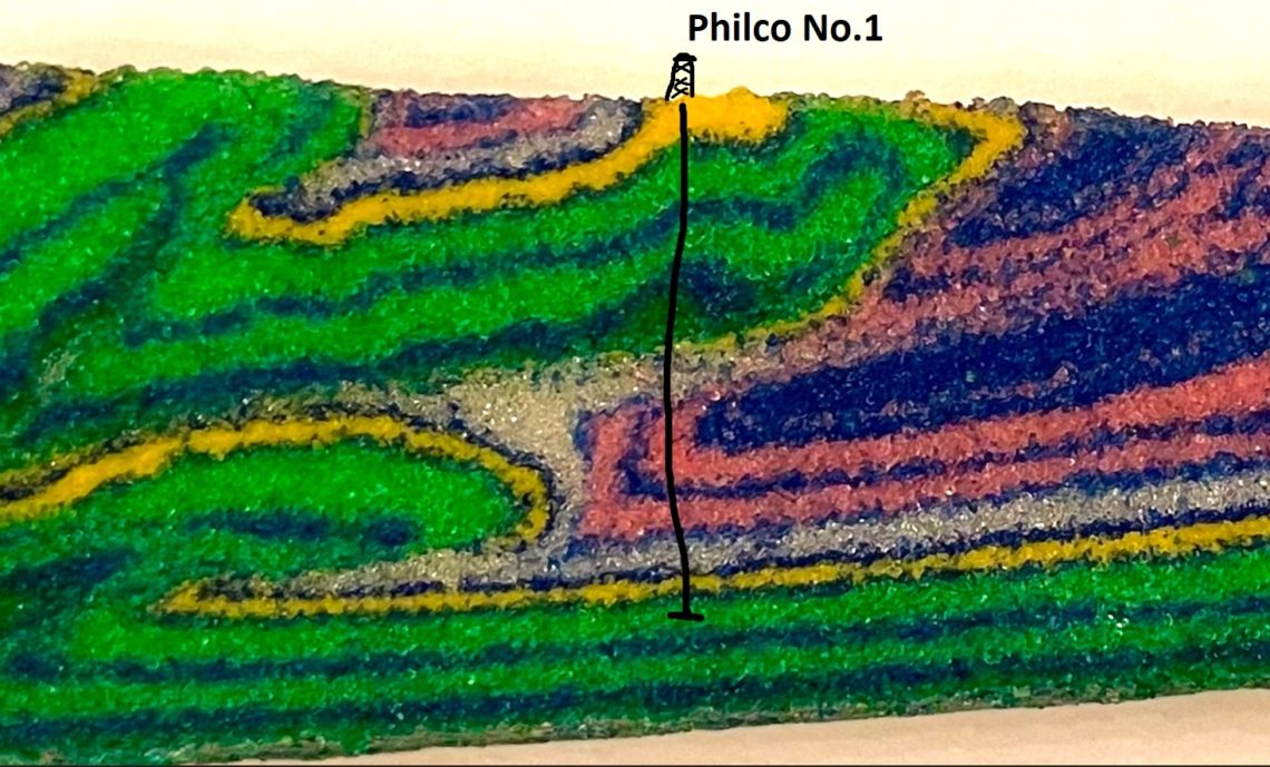
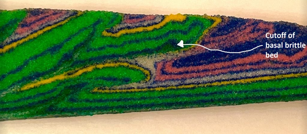
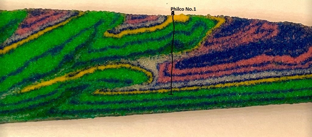
While the footwall of the Brazeau Thrust beneath the Ram River Anticline is generally intact and undeformed, the model’s thrust footwall hosts interesting upturned beds cut off by the thrust fault. Were the model a real thrust belt, drilling through the first anticline of the upper thrust sheet, through the thrust, and into the upturned footwall beds might be interesting, whether you’re into exploration or carbon storage. A hypothetical well is shown here…
…and after all of this, what was the intended, southern Appalachian-style model supposed to look like? Something like this, with a couple of thrust imbricates atop an undeformed flat footwall.

https://www.lyellcollection.org/doi/abs/10.1144/sp421.5
http://en.earth-science.net/en/article/doi/10.1007/s12583-017-0775-z