Negative inversion of a sandbox model thrust fault
by Philip S. Prince
Inversion of normal faults during compression is a popular topic in structural geology, but thrust or reverse faults can also be inverted by extension. Like inverting normal faults, favorable fault dips are an important part of this process, particularly when it is reproduced in a sandbox model like the one shown below.
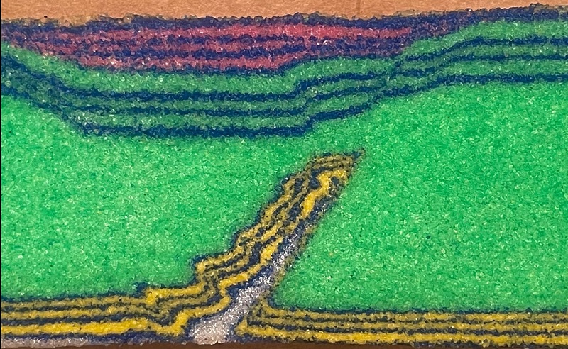
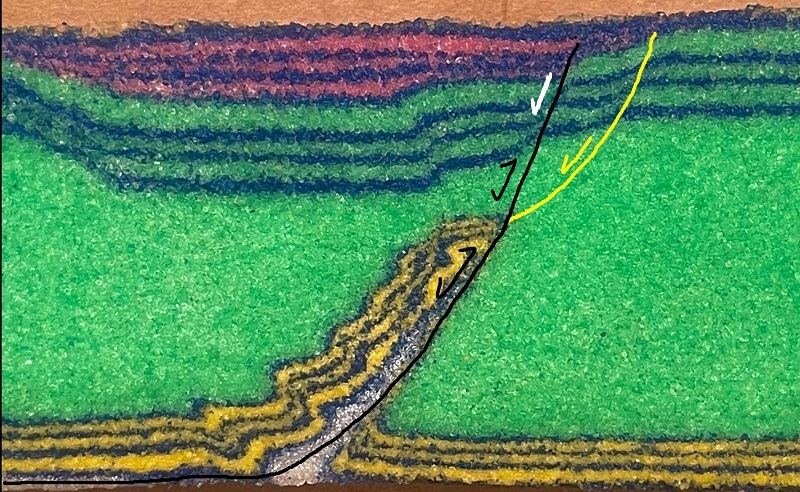
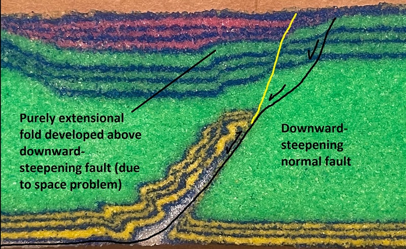
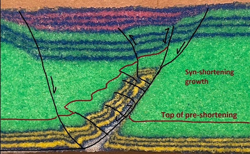
This model developed an initial steep thrust fault due to oblique shortening. The thrust, along which the yellow layer moved up-section, reactivated during direct extension to offset the interebedded green-blue and pink-blue horizons. These interbedded horizons post-date compression and pre-date extension. The annotated image below shows the main thrust fault beneath the displaced yellow interval and the associated extensional fault segments. The yellow fault segment was the first to move during initial extension; the black extension of the main thrust plane began moving later during the extensional phase. The white arrow indicates a purely extensional segment that expanded off of the existing thrust during reactivation…the layers it offsets were yet to be deposited during the compression/thrust phase.
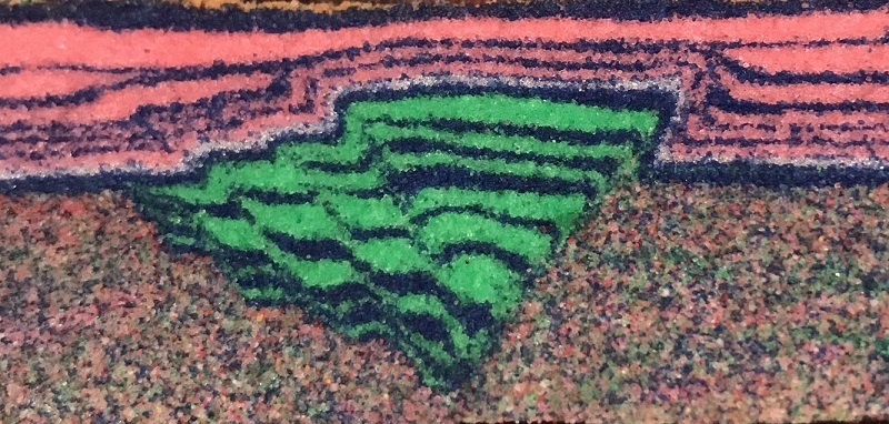
A particularly interesting detail of this model is the apparent reverse fault and gentle anticline in the blue-green section above the yellow thrust structure. Though it initially appears related to the thrust/compressional phase of the model, it is actually a purely extensional structure related to downward steepening of the initial extensional fault movement. The image below highlights the fault segments moving during initial extension; the abrupt downward steepening as the shallow fault deflects into the thrust plane forces the folding in the blue-green sequence.
Development of this model centers around the steepness of the initial compressional/thrust structure, which is steep because of the strongly oblique shortening that produced it. Direct shortening would have produced a shallower fault which would not reactivate during extension. The GIF below gives an overall sense of the orientation of oblique shortening, followed by direct extension.

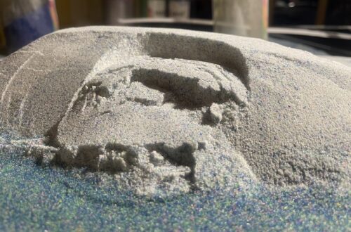
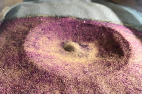
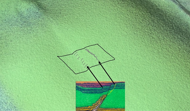
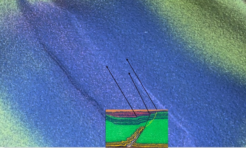
During the extensional phase, faint evidence of the various extensional fault strands and the associated folding can be seen on the surface of the model. In the images below, locations of these features are indicated on the cross section slice of the model already shown.
The deformation sequence of this model involved considerable syn-compressional deposition, with green sand deposited along the flanks of the growing thrust anticline. This setup was used to produce the final compressional geometry with the yellow interval on the thrust hanging wall, completely surrounded by green. The yellow sand (dolomite sand) is stronger and more brittle than the green sand (quartz sand), so this geometry produces an interesting strength contrast zone within the layer pack. Drawing faults and the location of the pre-shortening surface on the cross section would look something like the annotated image below.
This model is effectively the inverse of a normal fault reactivation or basin inversion setup, which would require direct extensional motion followed by oblique shortening to invert the existing normal faults. At least in the sandbox model world, both of these inversion approaches require oblique compression to produce thrust or reverse faults of sufficient steepness to match up with normal faults, whose dips are always steep in these models. A basin inversion model produced by the “inverse” of the setup shown here is seen below.
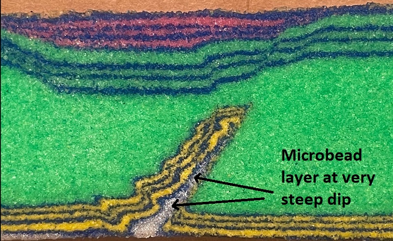
A detail of the thrust inversion setup that may impact the slightly lower dip of the initial normal fault segment is the presence of the weak microbead decollement layer on the thrust ramp. During shortening, the microbead layer is carried up the ramp. The microbeads have very low internal friction and are exceedingly unstable on the ramp at its high dip. As soon as compression is released and the layer pack can “relax,” collapse within the steeply dipping microbead horizon begins immediately.
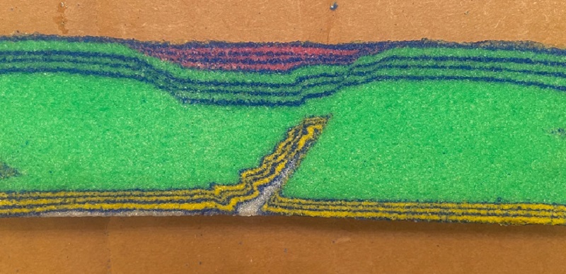
Finally, the overall appearance of the model slice is shown here. This setup consumes a regrettable amount of whatever color of sand is used for the growth sequence. The model was developed on a planar, flat base plate. The faint curve at the base seen here is the result of careless slicing and drying!
While this is a very idealized setup with a specific outcome in mind, structures like this do develop in settings where stress regimes can change significantly and the potential for rapid subsidence and syn-deformation deposition is high. Back-arc settings are a good example, as subduction angle, behavior of the sinking slab, shifts in orientation of plate motion, etc. can greatly alter deformational and depositional conditions in the overriding plate. Such a setting might experience extension and deposition, localize compressional inversion to produce isolated thrust structures like the one shown above, followed by a return to extensional or transtensional stress regime to cause collapse. I like this model because it nicely demonstrates the importance of stress field orientation and the independent variable of material strength on deformation patterns.