Interesting Reverse Faults in a Simple Extensional Sandbox Model
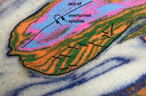
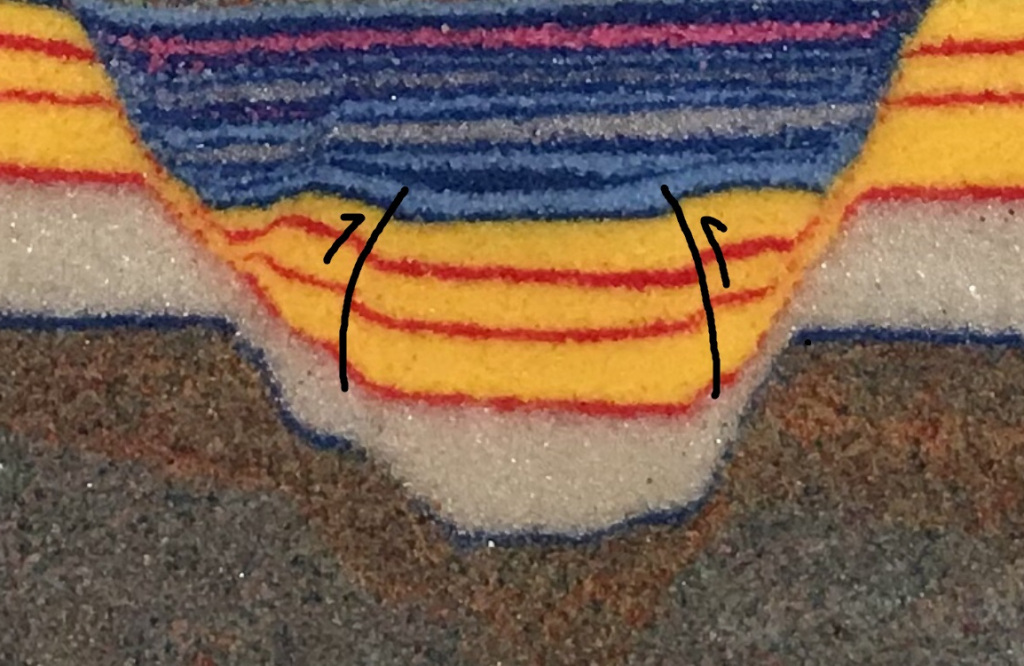
The model of extensional deformation shown here contains an unusual (?) detail that results from initial folding of the yellow and red layers before they were cut by faults. The model is dominated by normal faults, as one would expect from extensional deformation, but it also contains two minor reverse faults despite only experiencing extensional movement. The reverse faults show a tiny amount of displacement, but they are clearly visible as layer offsets at each end of the yellow and red layer zone in the graben (downthrown block).
The reverse faults are indicated by black lines in the image below; the black arrows indicate relative movement.
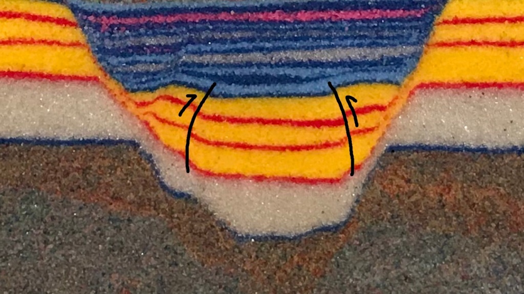
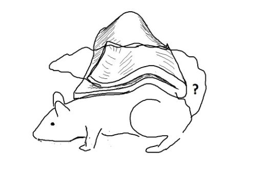
These minor reverse faults appear to result from fault propagation folding that occurred at the beginning of the deformation sequence. Tightening of the syncline (U-shaped fold) that forms as the model started to move caused localized compression in the inner hinges of the fold (see sketch below). The surface effects of the reverse faults can be seen in the moving GIF; the yellow arrow points to where the most obvious surface expression ended up once it dropped further into the basin and was buried (the GIF only shows the very beginning of the model run; it undergoes much more extension to make the final geometry shown in cross section). I don’t think that the reverse faults result from interaction of the yellow/red layers with the deep gray layer, as none of the basin fill layers show reverse fault disruption.

The line drawing below offers a general conceptual representation of where compression (squeezing) developed in the hinges of the fold. This compressional stress produced the small reverse faults; they are most definitely limited to these very loczalized zones in the model. Stretching indicated on the crests of the outer fold hinges causes cracking visible in the GIF above. The line drawing below only focuses on the yellow/red layer zone, which responded to initial normal faulting below it in the deep gray layers. The deep gray layers are intended to represent metamorphic or intrusive igneous “basement” rock.
Compression in the inner fold hinges is magnified by the thickness of the yellow sequence, which is a very strong, brittle sand, and the presence of the weak white microbead layer beneath it. The microbead layer allows the yellow layer to initially fold when the model starts moving. Without the microbead layer, faults would cut through all layers at the onset of movement. In the layer sequence used here, the weak microbead layer disconnects the deep strong layer from the yellow/red layers, allowing the initial fold to develop before faulting ultimately breaks through to the surface.
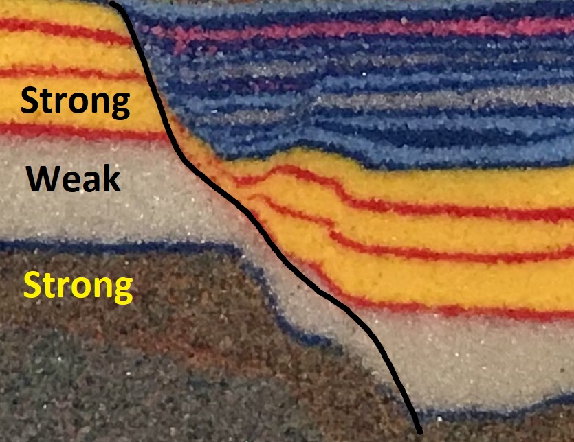
The different mechanical properties of the layers are apparent in the dip angles of the normal faults in the model. The master fault on the left side of the model (black line) is less steep in the weak microbeads, an expression of how their failure behavior differs from the stronger layers above and below. The anticline (convex-up fold) in the yellow sequence at the center of the image is a result of the shallowing of the master fault (more on this in another post).
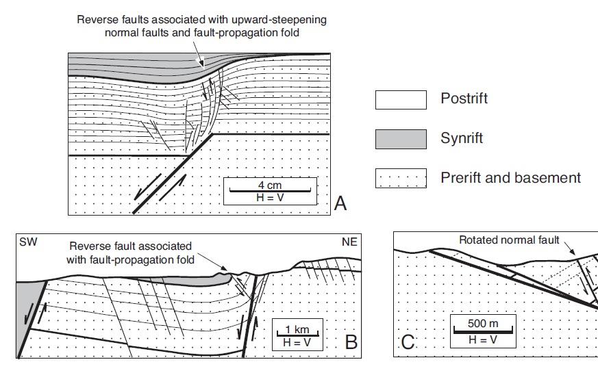
Simple models like this one are difficult to specifically scale to particular tectonic examples, but the basic geometric relationships that develop in the model do have documented analogs. The images below are from Figure 10 of Withjack et al. (2002), available at this link. It shows similar small reverse faults in a clay cake model (A) and a real-world example from the Suez Rift Basin (B).